Gate Valves : Gate Design

The most common gate designs available in the gate valve are the wedge gates, so called because in cross-section they are shaped like wedges. They are used in conjunction with two body seats set at anqles of from 3° to 6° to the stem centerline. The wedging action obtained when closing the valve forces the gate tightly against both seats, producing two sealing surfaces and making the valve tight against flow in either direction.

Three styles of wedge gates are available:

  • the one-piece solid (commonly known as a solid wedge),
  • the one-piece flexible (commonly known as a flex wedge), and
  • the two-piece spilt wedge.

  • 1. the one-piece solid (commonly known as a solid wedge),

      The solid wedge gate was, at one time, the most frequently used design. It is still the simplest, most economical style and is the most resistant to corrosion and vibration. It is also ideal for steam service and turbulent flow. A solid wedge gate, modified by adding a stem cavity, is used with the NRS. It is the standard on bronze, cast iron, and small steel valves.

      The drawback of the solid wedge gate is its rigidity, which does not allow it to accommodate seat distortion and makes it prone to sticking when subjected to temperature extremes. In addition, sealing depends on precise machining and filling of the wedge and body seating surfaces. The larger the valve, the more difficult it is to obtain a good fit with the solid wedge gate. Consequently, it is not readily available in large steel valves.
    2. the one-piece flexible (commonly known as a flex wedge),
      The flex wedge gate is cast with a circumferential groove around its perimeter or one is machined into it. This groove produces the flexibility that allows the seating surfaces of the wedge to move independently and adapt to minor inaccuracies in seating-surface angles and movement of the valve seats owing to pipeline loads or thermal expansion of the piping system.
      It minimizes wedge sticking when the valve is closed when hot and opened when cold. This ability to flex while retaining one-piece construction makes the flex-wedge design the best one for most applications. It is now the standard for large steel valves.
    3. the two-piece spilt wedge.
      The split wedge gate is made in two parts with a ball-and-socket type joint between them, thereby providing complete flexibility to compensate for seat movement andseat angle machining tolerances. The split wedge gate is found on small bronzevalves in which the flex wedge is not practical and on large valves made of stainlesssteel and other expensive materials.
      In the case of expensive materials, it is more economical to provide split wedge gates than the thick body walls needed to resist seat movement owing to line loads and thermal expansion. The split wedge gate is not recommended for high velocity or turbulent flow in which the two halves could vibrate and chaffer.

    Wedge gates are typically guided by ribs located either in the valve body or on the wedge, and fithng into mating slots in the sides of the wedge or in the valve body, respectively.

    All gate designs are used with body seats that are either integral with the body (machined surfaces on the body), separate seat rings pressed or screwed into the body, or hard material weld overlayed in the valve body and then machined as an integral seat. For steel valves, which are used in high-temperature and high-pressure applications, the separate seat rings are also seal-welded to the body. This ensures against leakage between the body and the seat ring.




        Read More....

        Gate Valves : Stem Design

        Gate Valves are available with three stem designs:
        1. inside screw rising stem (lSR)
        2. non-rising stem (NRS), and
        3. outside screw and yoke (OS&Y).

        1. Inside Screw Rising Stem (ISR)

        • The inside screw rising stem (ISRS) is shown in Figure 2.2. The right-hand thread on the stem mates with an internal thread in the bonnet so that by turning the valve hand wheel clockwise the stem and gate are translated downward, closing the valve.
        • The height of the stem outside the valve indicates whether the valve is open or closed. The ISRS usually used only on bronze valves.

        2. Non-Rising Stem (NRS)

        • A non-rising stem (NRS) is shown in Figure 2.6. This design is used where insufficient space above the valve limits stem movement upward. In this case a left-hand thread pn the stem mates with an internal thread in the gate. An integral stem collar held in the bonnet keeps the stem from moving up or down but permits it to turn. A left-hand thread is used so that turning the handwheel clockwise closes the valve. Because the stem does not move upward, it can not be used to determine whether the valve is open or closed. The NRS usually is found only on bronze and cast iron valves.
        3. Uutside Screw and Yoke (OS&Y).

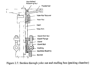
        • The outside-screwand-yoke (OS&Y) design shown in Figure 2.7 prevents thread wetting because the threaded portion of the stem is outside the valve. The stem passes through a yoke, which is formed by two arms that extend up from the bonnet and joint to form a housing for a yoke nut (also called a stem nut, yoke bushing, or stem bushing). Unlike the other stem designs, the hand wheel is attached to the yoke nut rather than to the stem. The yoke nut is free to turn but is held in place at the top of the yoke by a yoke-nut retainer, which also acts as a bushing for the nut. The yoke nut has a left-hand internal thread that mates with the thread on the stem. The stem thread is left-handed so that turning the hand wheel clockwise moves the stem downward, closing the valve. In this design the stem does not turn and may be pinned to the gate; The position of the gate within the valve is easily determined from the position of the top of the stem. The OS&Y design is standard for all sizes of cast iron and steel gate valves.

        In all three stem designs, external leakage along the stem is prevented by the use of deformable non-metallic packing. The packing is located in the bonnet in a circular cavity commonly known as the stuffin box or packing chamber. In valves using ISRS and NRS stem designs, the packing is held in place by a tubular gland backed by a hollow packing nut that threads onto the top of the bonnet. In valves using the OS&Y stem design, the packing arrangement is more complicated. The packing is held in place by a gland, which is backed by a gland flange. The gland flange is restrained by a pair of gland bolts and nuts, which are, in turn, fastened to the bonnet using eyes and pins or some comparable arrangement.


        Read More....

        Gate Valve : Body-Bonnet Joint Design

        The available designs of body joints are screwed, union, bolted-bonnet. pressure-seal, and welded-bonnet joints.

        • The screwed joint is shown in Figure 2.2. The male thread on the bottom of the bonnet screws into the female thread in the top of the body. It is used on small bronze valves.


        • The union joint is shown in Figure 2.3. As in a pipe union, a female-threaded nut locks the unthreaded bonnet against the male-threaded body. It has an advantage over the screwed joint because the body and bonnet sealing surfaces do not rub together and wear when the joint is being tightened. This makes it preferable to the screwed joint when disassembly is necessary. Because of the high torque required to assemble or remove the union nut, the union joint is limited to use on small valves.


        • The bolted-bonnet joint shown in Figure 2.1 has mating flanges on the body and bonnet that are held together with studs or bolts and nuts, On small valves, it is common to have the bonnet held on : bofts that screw directly into threaded holes in the top of the body. A gasket is placed between the flanges to prevent leakage. Depending on the pressure capability of the valve, the gasket can be flat, solid material: filled spiral-wound material; or a metal ring. Flat gaskets are found on low-pressure valves; whereas spiral-wound gaskets and metal rings are used on medium- and high-pressure valves. Bolted-bonnet joints can •be readily disassembled for repair and are used on all sizes of cast iron and steel valves.


        • The pressure-seal joint is shown in Figure 2.4. In this design, internal pressure against the bottom of the bonnet causes it to press against a relatively soft seal ring. Because of its wedge-shaped cross-section, the seal ring deforms to press tightly against both the outside surface of the bonnet and the bore of the body, sealing the joint. The segmented thrust ring, which is held in a circular groove at the top of the body, absorbs all the thrust applied by the internal pressure. The hardened spacer ring between the seal ring and the thrust ring prevents deformation of the top of the seal ring. The retaining studs of the bonnet hold it in place and apply a preload to the seal ring before the valve is put into service. Pressure-seal joints are used on steel valves for high and very high pressure service.


        • A welded joint is shown in Figure 2.5. Welding the bonnet to the body ensures against leakage at the joint but makes disassembly of the valve much more difficult. The welded bonnet produces a lighter valve than does the bolted bonnet or the pressure seal. This joint is usually found only on small steel valves.
        Read More....

        Gate Valves : Typical Design


        The Figure shows a typical gate valve.

        A manufacturer might describe this valve as a “flanged end, bolted-bonnet, outside-screw-and-yoke, flex-wedge, gate valve.”


        Read More....

        Gate Valves : Function

        The flow control element of a gate valve (called a gate, wedge, or slide) enters the fluid path from the side and traverses it until the fluid .path is completely closed off, stopping the flow.
        When the valve is open, the gate is entirely out of the fluid path. Thus flow is in a straight line, with very little resistance from the valve. Because the gate valve is symmetrical, either end can be the inlet, and thus flow can be from either direction through the valve (BIDIRECTIONAL VALVE).
        The form of control for which gate valves are suited is starting and stopping flow. Gate valves, as are other valve types used for this kind of control, are frequently referred to stop valves or block valves.
        Read More....

        Types and Styles of Valves in Oil & Gas Operation

        There are many types of valves; however, those used in industrial and power piping applications are almost always one of the following valve types:
        • gate,
        • globe,
        • check,
        • butterfly,
        • ball,
        • plug, or
        • diaphragm.

        In the process of performing its control function, a valve must satisfy two conditions.

        • First, the fluid cannot be allowed to leak into the environment.
        • Second, there can be no internal leakage.

        That is, when the valve is closed there can be no flow, either along the normal fluid path or between valve parts, where flow is never intended. These two conditions are not always met absolutely. Valve testing standards, such as the American Petroleum Institute Standard API 598, permit a very small amount of leakage at the seating surfaces for some types and sizes of valves.

        All valve types are manufactured with ends that mate with the common piping connection methods:

        • threaded (also called screwed),
        • flanged,
        • butt-weld
        • socket-weld.
        • solder, and
        • grooved.

        The appropriate connection method to be used on the valves in a specific pipeline is decided by the piping designer.

        The designers decision is based on factors such as line size, fluid pressure, materials of construction, and ease of assembly. Small valves are usually manufactured with threaded or socket-weld ends; whereas large valves are usually manufactured with flanged or butt-weld prepared ends.

        Some valves are made with no “ends.” There are two different styles, wafer valves and lug valves, both of which are designed to be used with flanges.

        The wafer-style valve is used between mating flanges. Its circular body fits just inside the circular bolting pattern of the flanges. When tightened, the extended-lenqth flange stud bolts cause the flanges to seal the ends of the valve and hold the valve in position.

        The lug-style valve is also circular but has projections (called lugs) with threaded holes spaced around its perimeter. The locations of the holes match those of the mating flanges, and the threads match the flange stud bolts used in assembly. The lug-style valve can be situated between flanges by using short stud bolts with each flange, with the valve body acting to hold the pipeline together, or the lug valve can be bolted to a single flange at the end of a pipeline.

        Read More....

        The Function of Valves in Oil & Gas Drilling & Production

        A valve is a mechanical device whose function is to control the flow of fluids in piping systems.
        The fluids controlled in industrial settings can be the common liquids, gases, and vapors; but they also can be liquids carrying suspended solid particles (called slurries) and gases carrying suspended solid particles.
        The control applied to these fluids can take one or more of the following forms:
        1. Starting and stopping flow— (Gate, Ball, Butterfly, Diaphragm)
        2. Regulating flow volume (frequently called throttling)— (Globe, Butterfly, Diaphragm)
        3. Preventing reverse flow (called anti-backflow)---- (Check)
        4. Changing flow direction— (Multi Pod Plug, Multi Port Ball)
        5. Limiting fluid pressure— (Safe & Relief)

        A valve performs its control function by placing an obstruction (hereafter called the flow control element) in the fluid path through the valve.

        The nature of the flow control element determines the valve type and the form of control for which the valve is suited.

        Read More....